How to Install a PlugStream Charge Point
Introduction
This guide covers the physical installation of a PlugStream Charge Point: mounting the unit, connecting the mains supply, confirming upstream protection, fitting an Aux CT where required, preparing the network route, and powering the charger ready for commissioning.
The leaflet supplied with each charge point links to this page. Keep this URL for the site installation steps, then continue into the Installer app article for commissioning, tests, evidence upload, and customer handover.
Installer app commissioning and handover
After the charger is mounted, wired, checked, and powered on, follow How to use the PlugStream Installer app. That article covers Bluetooth commissioning, network checks, photo evidence, charger tests, sign-off, and the customer handover QR/link.
Before proceeding, installers should be familiar with these guides:
- Preparing the site
- Tools required
- Installation height
- Mounting the device
- Network setup
- How to use the PlugStream Installer app
Installation Video
Watch the full installation walkthrough below, or open the video on YouTube.
Safety and Electrical Requirements
Installation must only be carried out by an authorised installer. Isolate the supply before opening or working on the charge point, and complete all required electrical checks before energising the unit.
PlugStream includes built-in 6mA DC ground-fault protection to IEC 62955, but the charge point and upstream circuit must also be protected against AC ground faults.
Install and confirm:
- a suitable upstream circuit breaker
- a 40A Type A RCD upstream of the charge point
- correct earthing and polarity
- earth loop / impedance checks
- PEN fault verification where required by the installation design
- protective device and max supply values for installer app sign-off
Earth cable
Do not route the earth cable through the RCD module. This will impair correct operation.
Physical Installation Steps
1. Prepare the Site and Isolate the Supply
- Confirm the customer, site address, installation position, network route, and access are ready.
- Confirm whether site load management or an Aux CT is required.
- Confirm the wall, pedestal, cable route, isolator, and consumer unit are accessible.
- If an Aux CT is required, confirm whether it will connect to a PlugStream Flow node or directly to the charge point Aux CT terminal.
- Isolate the supply and verify it is safe to work before opening the charger.
2. Mount the Charge Point
- Remove the front cover by undoing the two Allen key bolts at the top and bottom.
- Position the supplied wall-mount bracket and use its mounting holes as the drilling guide.
- Install the bracket using the supplied fixings.
- Check the bracket is level and mounted at the agreed height. The minimum mounting height is 0.9 m from ground level.
- Mount and secure the charge point on the bracket.
- Confirm the cable entry, seals, fixings, and enclosure are correctly seated.
For more detail, see Mounting the device and Installation height.
3. Connect the Mains Supply
- Bring the supply cable into the charger through the approved cable entry.
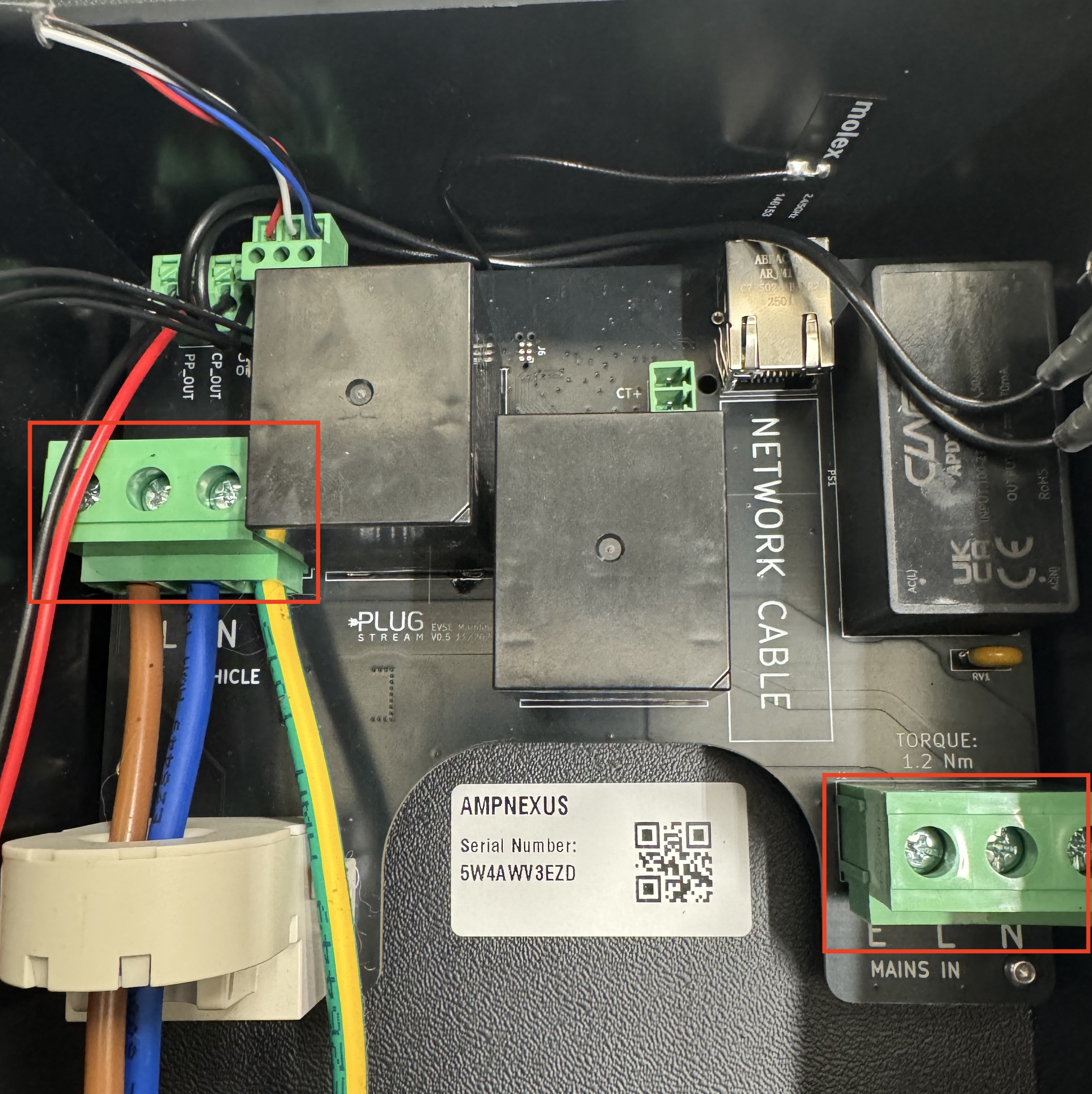
- Connect live, neutral, and earth to the correct terminals.
- Tighten each terminal screw to the torque value printed on the PCB. Where marked, use 1.2 Nm.
- Check the earth routing before closing the charger.
4. Confirm Upstream Protection
Before power-on, confirm the upstream protective devices are installed, correctly rated, accessible, and labelled.
The Installer app will ask for the protective device rating and max supply value during sign-off, so keep these values available.
5. Install the Aux CT Clamp, if Required
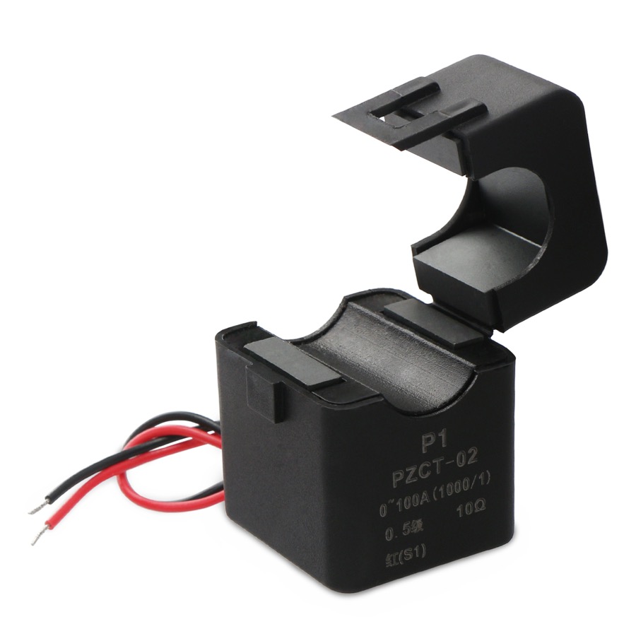
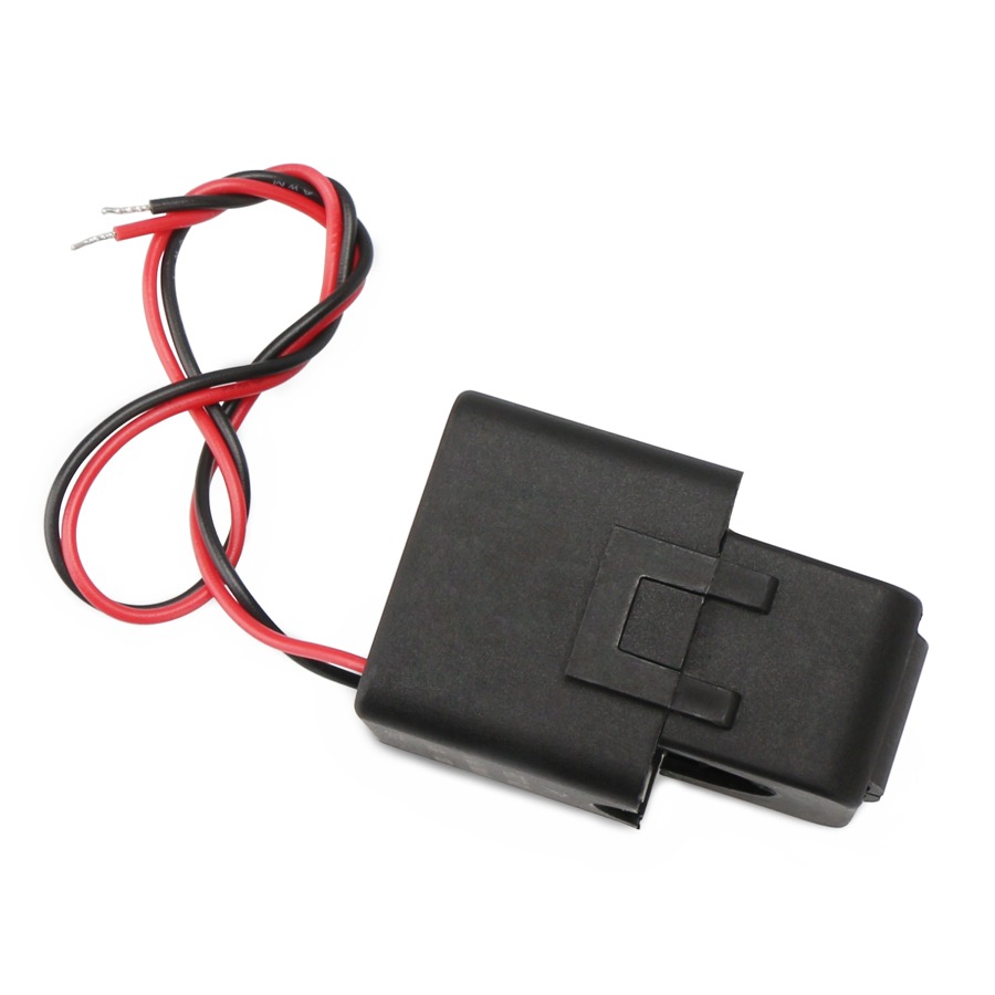
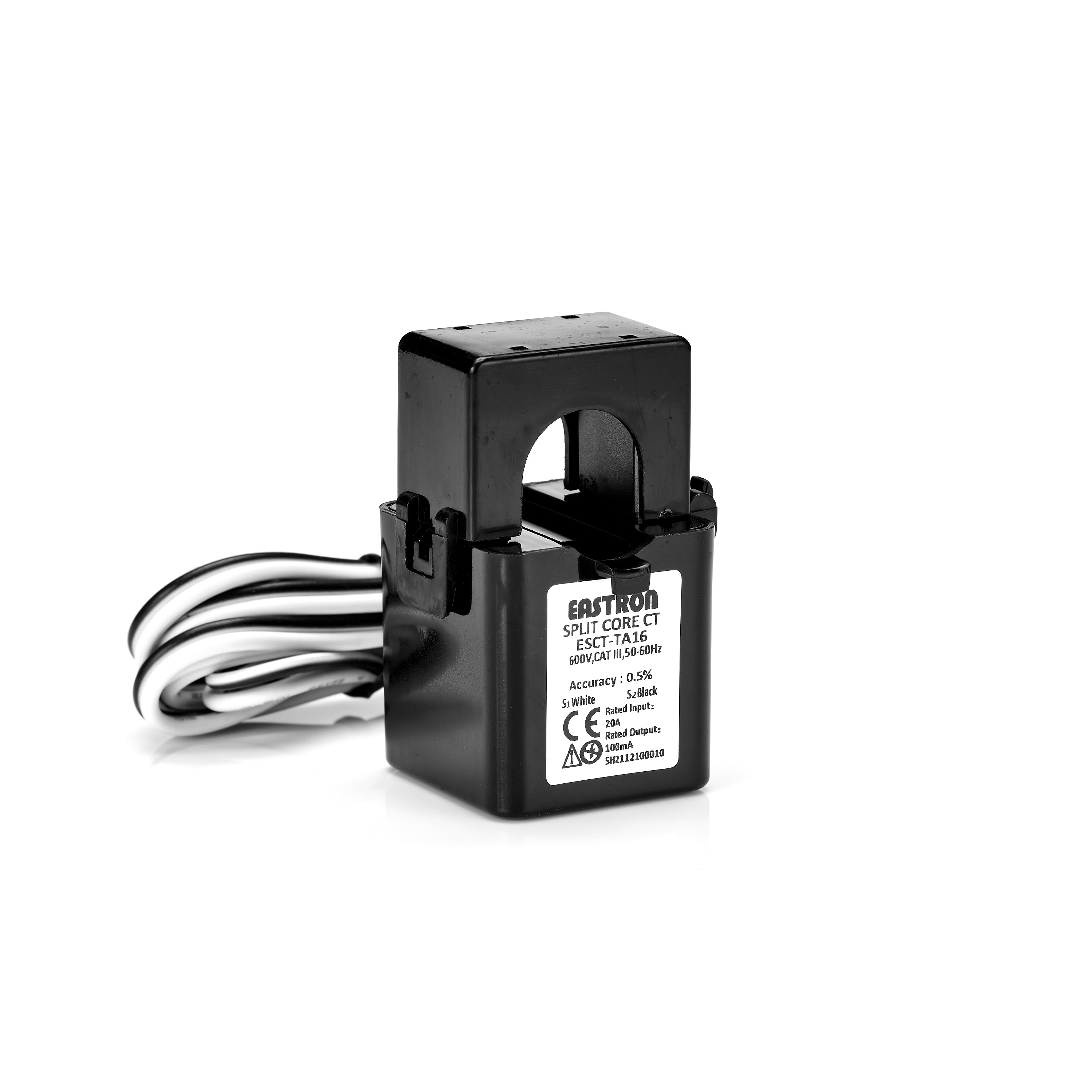
Install the Aux CT only where the site design requires site load management or a whole-site current reading. PlugStream supports the supplied 100A/100mA current-output Aux CT options below. Both options are 1000:1 CTs; the rating printed on the actual supplied CT must match the job paperwork.
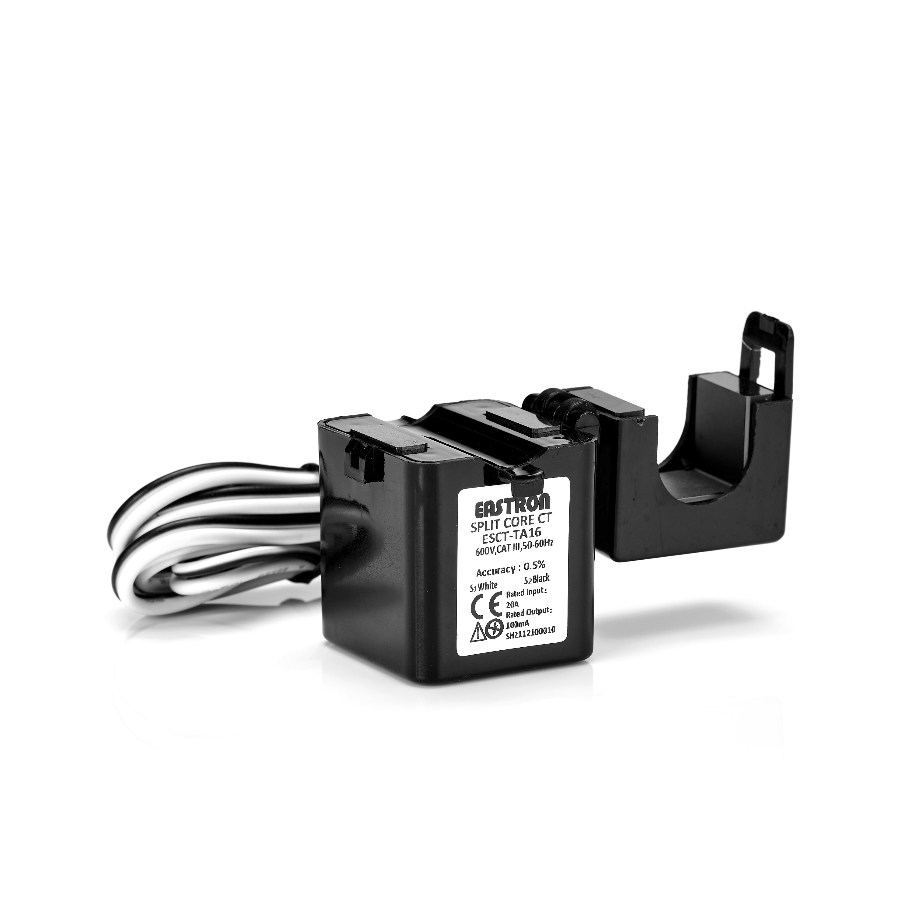
Current-output CT safety
Do not leave a current-output CT secondary open-circuit while it is clamped around an energised conductor. Keep the CT plugged into the Flow node, wired into the charge point Aux CT terminal, or safely shorted during work.
Fit the CT clamp as follows:
- Fit the CT around the single live conductor being monitored. Do not clamp around live and neutral together.
- For whole-site load management, fit the CT on the incoming live tail so it measures the site load, not only the charger supply.
- Orient the CT arrow from the supply / meter / main fuse side towards the consumer unit / site load side. If the CT body is marked
P1instead of an arrow, faceP1towards the supply / meter / main fuse side. - Close the split core fully and confirm the latch is secure.
- Keep the CT cable route protected, labelled, and separated from mains wiring unless the wiring system and insulation are suitable for the environment.
If the CT is being used with a PlugStream Flow node, leave any supplied white connector fitted and plug it into the correct Flow node CT input. If the CT is supplied with bare tails, fit the approved Flow CT connector or harness before plugging it into the Flow node.
If the CT is being wired directly to the PlugStream charge point Aux CT input:
- Confirm which supplied CT is fitted before cutting or extending the cable.
- Cut off any supplied white connector only after recording the
S1andS2core colours for that CT. - Extend the CT using a suitable two-core cable or twisted pair, keeping the extension as short as practical.
- Maintain polarity end to end:
S1must remain the same conductor at the charge point, andS2must remain the other conductor. - Make extension joints in a suitable insulated enclosure or terminal block, and label the CT pair for future service work.
- Bring the CT extension into the charger through a suitable cable entry without compromising the enclosure seal.
Wire the charge point Aux CT terminal as follows:
| Supplied CT | CT core | Aux CT terminal |
|---|---|---|
| DROK 100A/100mA | S1 Red |
Pin 1 / AUX_CT / sense |
| DROK 100A/100mA | S2 Black |
Pin 2 / AUX_CT_MID / return |
| Eastron ESCT-TA16 100A/100mA | S1 White |
Pin 1 / AUX_CT / sense |
| Eastron ESCT-TA16 100A/100mA | S2 Black |
Pin 2 / AUX_CT_MID / return |
| Either supplied two-core CT | No CT core | Pin 3 / GND - leave unused |
Before closing the charger, gently tug-test the CT conductors and confirm there are no loose strands or trapped cables.
During commissioning, enable Aux CT only when the clamp is fitted. With the site importing power, the Aux CT current and power should read positive in the Installer app. If the reading is negative while the site is importing, stop and correct the CT polarity by checking the clamp direction and the S1 / S2 wiring before handover.
6. Prepare the Network Route
PlugStream supports Bluetooth, Wi-Fi, Ethernet, and 4G with the optional mobile add-on card.
Choose and prepare one route before commissioning:
- Ethernet: recommended for the most stable PlugStream Cloud connection. Connect and test the Ethernet route before handover.
- Wi-Fi: confirm the SSID and password are available at the charger location. The Installer app can guide Wi-Fi setup over Bluetooth.
- Mobile: confirm the optional mobile card is fitted and the site has usable signal.
For firewall, DNS, DHCP, and internet requirements, see Network setup and Network Requirements for PlugStream.
7. Capture Installation Evidence Photos
Capture these photos before closing the charger if the view will be harder to access later:
| Photo | What to show |
|---|---|
| Charger front | A straight-on photo showing the installed charger body. |
| Serial / rating marking | The laser-etched marking on the enclosure front with the serial and rating legible. It is not on the removable face cover. |
| PCB wiring | The wired PCB, supply terminals, earth routing, and cable entry before the cover is closed. |
| Aux CT, if fitted | The CT clamp location, arrow direction, extension joint if used, and Aux CT terminal wiring. |
| Consumer unit / isolator | The protective device or isolator serving the charger. |
| Installed context | A wider shot showing the charger in its finished install location. |
The Installer app can upload these photos during commissioning. If mobile upload is unavailable on site, photos can be deferred, but the installer warranty remains pending until the required evidence is uploaded.
8. Refit the Cover and Power On
- Refit the cover and confirm the enclosure is secure.
- Re-check isolation, polarity, earthing, protective devices, Aux CT wiring if fitted, and any site-specific requirements.
- Switch on the upstream circuit breaker when installation checks are complete.
- Keep the laser-etched charger marking, isolation point, and test equipment accessible for app commissioning.
The status indicator will show:
- rainbow pattern during self-test
- pulsing white until an internet connection is established
- solid blue once connected to PlugStream Cloud
For LED behaviour, see LED Status Guide.
Activation and network connection
A network connection and activation are required for PlugStream smart features such as remote control, scheduling, monitoring, installer evidence, and customer handover. The charge point can still operate as a basic charger without smart features, but the installer app workflow should be completed where installer commissioning and handover are required.
Continue to Commissioning
When the charger is mounted, wired, protected, checked, photographed, and powered on, continue with How to use the PlugStream Installer app.
The app will guide you through Bluetooth commissioning, customer assignment, firmware readiness, installation evidence, live checks, charge testing, electrical sign-off, and customer handover.
Support
If you have any questions or require assistance with installation, contact PlugStream Support:
0300 180 0403